
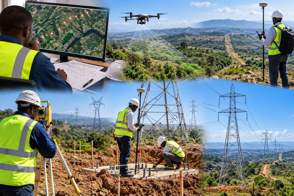
What Surveyors Do on a Power Line Project, From Route Selection to Tower Setting Out

Apex Surveyors Team
When people see a transmission line marching across the landscape, they usually think about the towers and the cables. What they don’t see is the survey work that decided where every tower stands, how high every conductor hangs, and which fields, roads and rivers the line crosses on the way.
Surveyors are involved from the first sketch on a map to the last tower pegged on the ground. A power line project can run for dozens or even hundreds of kilometres, and a small error at the start can multiply along the way. Getting the survey right is what keeps the line safe, buildable and on budget.
Our team has worked on power transmission projects in Kenya and Tanzania, and on utility and grid alignment work in South Sudan. This guide walks through what surveyors actually do at each stage, in plain language, whether you’re a client, an engineer or a contractor.
Why Power Line Surveys Are Different
A building site is a few thousand square metres. A power line is a long, thin strip that can cross swamp, farmland, forest, rivers, roads, railways and other utilities, sometimes in the same kilometre.
That brings a few unique challenges:
- Distance. Errors in coordinates or levels can build up over long routes.
- Changing terrain. The ground might be flat, hilly or waterlogged within a short stretch.
- Access. Many sites are remote, with poor roads and little mobile coverage.
- Crossings. Roads, rivers, railways and other lines all need careful measurement.
- Third parties. Landowners, communities and authorities are affected, so accurate records matter.
- Safety. Clearances between conductors and the ground, trees, buildings and other lines are critical.
Each of those problems is a survey problem first.
Stage 1: Desk Study and Route Selection
Before anyone goes to the field, the project team looks at the corridor on paper and on screen. Surveyors and engineers study maps, satellite imagery, existing survey data and any constraints already known, such as protected areas, settlements, airstrips, rivers and existing infrastructure.
The goal is to find a route that is as short and direct as practical, while avoiding obstacles and keeping construction and maintenance manageable. A straight line is cheapest in theory, but real routes bend to avoid homes, wetlands, steep slopes, unstable ground and sensitive sites.
At this stage, surveyors often:
- Review satellite and aerial imagery to identify possible corridors
- Check existing mapping and coordinate information
- Mark candidate routes and points of concern
- Flag likely river, road and railway crossings
- Estimate lengths and rough terrain conditions
Drone mapping is increasingly helpful here, especially for areas that are hard to reach on foot. Our post on drone surveys in Juba explains where aerial data adds the most value.
Stage 2: Reconnaissance
Maps only tell part of the story. Reconnaissance, or “recce,” means walking and driving the proposed corridor to see what’s really there.
During the recce, surveyors check:
- Whether the proposed route is physically accessible
- Where roads and tracks reach, and where new access will be needed
- Real ground conditions: swamp, rock, dense vegetation, farmland
- Buildings, boreholes, graves, schools, places of worship and other features not visible on maps
- Obstacles such as existing power lines, pipelines and telecoms cables
- Practical locations for key points along the route
Recce findings often change the route. A hill that looked fine on a map may have a cliff on one side. A “clear” field may turn out to be seasonal swamp. Better to discover it now than after pegs and foundations are in.
Stage 3: Setting Control Along the Corridor
To keep a long line accurate, everything has to tie back to a reliable network of control points.
Surveyors establish control along the route using GNSS equipment, placing reference points at regular intervals. These give known coordinates and heights that every later measurement is checked against. In South Sudan, work typically uses the UTM grid (zones 35N and 36N cover much of the country), and keeping everyone in the same coordinate system matters for design, setting out and records.
Good control is the quiet hero of a long-corridor project. It stops small errors from drifting over kilometres, and it lets different teams work on different sections without their work failing to line up.
If you’re wondering which instruments suit which tasks, our upcoming guide on RTK vs total station will cover the trade-offs, and you can browse the equipment catalog for GNSS and other instruments we supply.
Stage 4: Route Survey and Centreline Marking
Once the route is agreed, surveyors mark and measure it on the ground. This is the core route survey, and the basis for engineering design.
Key tasks include:
- Marking the centreline, the path the line will follow, with pegs at regular intervals
- Identifying angle points, where the line changes direction (these usually become angle towers)
- Recording ground levels along the centreline, creating a longitudinal profile
- Measuring cross-sections where the ground slopes sharply across the route
- Recording features within the corridor, such as buildings, trees, roads, drains and fences
The centreline data becomes a plan and profile drawing: a bird’s-eye view of the route, and a side-on view of the ground along it. Engineers use these to work out tower heights, spacing and conductor clearances.
For a deeper look at how corridor surveys work in general, read our post on route surveys for roads, power lines, railways, runways, sewer and water lines.
Stage 5: Crossings and Third-Party Features
Where a power line crosses something else, accuracy is essential, both for design and for safety.
Surveyors carefully measure:
- Roads and railways, including levels, widths and clearances
- Rivers and streams, with banks, water levels and flood indicators
- Other power lines, recording their positions, heights and crossing angles
- Telecom lines, pipelines and other utilities within the corridor
- Buildings and structures close to the route
- Trees and vegetation that could encroach on the line
Crossing data lets the designer set tower positions and heights so the conductors stay safely clear, and it supports agreements with other utility owners and authorities.
Stage 6: Corridor and Wayleave Information
A power line needs a clear strip of land, often called a wayleave or right of way, and that strip affects landowners and communities. Surveyors provide the measurements that make it manageable:
- Recording the corridor width and position
- Identifying affected plots and landholdings
- Measuring where the line, towers and access tracks fall on each property
- Supporting accurate records for notices, agreements and compensation processes
Clear, accurate corridor data reduces disputes. Because boundary questions can arise in this stage, it often connects to the work described in our post on property, title and boundary surveys.
Stage 7: Tower Spotting (Positioning the Towers)
With the profile and crossings in hand, engineers decide where each tower should go. This step is often called tower spotting or structure spotting, and it’s usually done in specialist line design software.
The design team balances several things:
- Ground clearance. Conductors must stay at safe minimum heights above the ground, roads, buildings and other lines.
- Span lengths. Towers shouldn’t be spaced further apart than the design allows.
- Terrain. Towers sit best on stable, accessible ground, not in swamp, steep drops or flood channels.
- Angles. Direction changes call for stronger angle towers at the right locations.
- Access and cost. Easier locations are cheaper to build and maintain.
Surveyors support this stage by providing the accurate profile data, and by checking proposed tower positions against what’s really on the ground. Sometimes a site visit shows that a planned tower location is unsuitable, and the position is adjusted.
Stage 8: Detail Surveys at Tower Sites
Each tower site needs enough detail for the foundation design and construction. At each location, surveyors typically capture:
- A topographic survey of the tower footprint and surrounding area
- Ground levels and slopes across the site
- Access routes and approach conditions
- Nearby features such as drains, streams and boundaries
Sloping or uneven ground may need extra levels so the design allows for different leg heights or earthworks. Our post on topographic surveys before construction explains why this kind of data matters, and if you’d like to read the results confidently, see our guide to reading a topographic survey map.
Stage 9: Tower Setting Out
This is the moment the design becomes physical. Tower setting out means marking the exact position and orientation of each tower on the ground, so the foundation crew builds in the right place.
For each tower, surveyors typically:
- Set the tower centre point using the design coordinates
- Mark the leg positions, the points where each foundation will go, based on the tower’s base dimensions
- Establish the orientation, so the tower faces the correct direction along the line
- Set reference pegs (offsets) outside the excavation area, so the layout can be recovered after digging begins
- Transfer levels so each leg is excavated to the correct depth
- Check dimensions, including diagonals and distances between legs, to confirm the layout is square and correct
Because towers have several legs that must line up precisely with each other, small errors matter. A leg a few centimetres out of position can cause problems when the steel is assembled. That’s why setting out is checked before excavation, before concrete and again as the foundation takes shape.
Our guide to construction setting out explains the same principles on a building site, and the thinking is very similar for tower foundations. We also provide dedicated foundation setting out services.
Stage 10: Monitoring, Checks and As-Built Surveys
Survey work doesn’t end when the pegs go in. During construction, surveyors:
- Re-check tower positions and levels as foundations are built
- Confirm that stub positions, bolt groups and levels match the design before steel is erected
- Support stringing work by checking clearances where required
- Record the final positions of towers and features
After construction, an as-built survey records exactly where everything ended up. That gives the owner an accurate record for operation, maintenance, future upgrades and handover. Read more in our post on why as-built, existing and final surveys keep projects accountable.
Tools Used on Power Line Surveys
Different tools suit different stages:
- GNSS (RTK) receivers for control, centreline marking, profile points and quick work across long, open stretches
- Total stations for detailed work at tower sites, crossings and areas with limited sky view
- Levels for accurate height control and transferring levels to foundations
- Drones for mapping hard-to-reach areas, reviewing corridors and reducing time on foot
- LiDAR for detailed terrain and vegetation data where high detail is needed. See our post on LiDAR and urban surveying accuracy for how it works.
- Mapping and CAD software to turn field data into plans, profiles and setting out files
Most projects use a mix, with GNSS and drones covering distance, and total stations and levels handling precision work at tower locations.
Common Mistakes on Power Line Projects
Skipping the recce. Maps miss swamps, new buildings and access problems. A walk of the route can save weeks of redesign.
Weak control. Poorly tied control causes errors that grow along the line and surface when sections fail to meet.
Ignoring crossings. An unmeasured road or river crossing can force late design changes.
Outdated data. Land and vegetation change quickly. Survey data that’s a year old can be wrong for design clearances.
Mixing coordinate systems. If design, survey and construction teams use different systems, towers can end up in the wrong place.
Losing setting out marks. Pegs get damaged by machines, livestock and weather. Offset marks and good records protect the layout.
Not checking before pouring. Concrete is permanent. Check leg positions and levels before it goes in.
Overlooking safety. Working near existing live lines needs permits, clearances and trained crews.
Challenges in East Africa and South Sudan
Our work on transmission and grid projects across Kenya, Tanzania and South Sudan has shown a few recurring realities:
- Seasonal access. Rainy seasons can close tracks, flood low ground and delay field work. Plan survey windows around the weather.
- Remote locations. Long distances and weak mobile coverage mean GNSS jobs often need their own base stations.
- Land and community issues. Clear communication with landowners and local leaders makes surveying smoother.
- Vegetation. Dense growth slows centreline clearing and affects GNSS performance.
- Logistics. Fuel, transport, accommodation and equipment support all need planning for field teams working far from town.
Local experience helps teams anticipate these issues rather than react to them.
Frequently Asked Questions
What is a power line survey?
It’s the set of surveys used to plan, design and build an electrical line. It includes route selection, centreline and profile surveys, crossing surveys, corridor and tower site surveys, tower setting out and final as-built records.
What is a route survey for a power line?
It’s the survey that measures the planned corridor, marking the centreline, recording ground levels, identifying angle points and capturing features and crossings. The result is a plan and profile drawing used for design.
What is tower spotting?
Tower spotting means choosing the positions and heights of towers along the profile, so that conductors keep safe clearances and towers sit on suitable ground. Engineers do this using survey data and specialist software.
What is tower setting out?
It’s marking each tower’s centre and leg positions on the ground based on the design, so the foundation crew builds in the right place at the right level and orientation.
How accurate does tower setting out need to be?
It depends on the tower type and the engineer’s specification. Leg positions and levels typically have tight tolerances because the steelwork has to fit. Your surveyor should confirm the required tolerance before work starts.
Can drones be used for power line surveys?
Yes. Drones are very useful for route planning, corridor mapping and inspecting hard-to-reach areas. They’re usually combined with ground control and ground-based surveys for precise setting out.
How long does a power line survey take?
It depends on route length, terrain, access, weather and the number of tower sites. Short lines may take weeks, and long transmission lines can take months. A recce helps give a realistic schedule.
Who is responsible for wayleave and landowner issues?
Usually the project owner or developer, supported by accurate corridor and plot data from the surveyor. Local regulations and procedures vary, so the legal side should be handled through the proper authorities.
Do you need a new survey if the project is delayed?
Often yes, at least partly. Vegetation, buildings and land use change over time, so older survey data should be checked before design or construction continues.
Which instrument is better for power line work, RTK or a total station?
Both. RTK suits control, corridors and open ground, while a total station suits tower sites and obstructed areas. Most projects use them together.
The Bottom Line
A power line project is a long chain of decisions, and surveyors help make every link in it reliable. They guide route selection, establish control, measure the corridor, record crossings, support tower design and set out each tower foundation. The better the survey, the fewer surprises on site.
If you’re planning a transmission or distribution project, or need utility alignment, corridor mapping or tower setting out, talk to us. We offer engineering surveying, infrastructure mapping, topographic surveying and aerial drone surveys across South Sudan, backed by over a decade of experience and 100+ completed projects. Learn more about us, visit Apex Surveyors, or browse more guides on our blog.
Teams that want to build their own capability can also look at our Professional Training.
Request a survey or call +211 928 765 792, and tell us about your route.
Related reading: Route surveys for roads, power lines, railways and more · Construction setting out explained · Drone surveys in Juba · More on the Apex Surveyors blog
Before you publish, please check these:
- As-built link. I guessed the slug for the as-built post (why-as-built-existing-and-final-surveys-keep-projects-accountable) from its title. Compare it with the live URL and correct it if needed.
- Real project detail. Your site only mentions “transmission grids” and utility and grid alignment, so I kept Kenya and Tanzania references general. If you can share details such as voltage class, line length, number of towers or your role (route survey, tower setting out or both), add one short project example. That would make this post far more credible. Only include what the client allows you to publish.
- UTM zones. I mentioned zones 35N and 36N because both appear on your homepage. Edit if you want to be more specific.
- Services I mentioned. Tower spotting support, wayleave data and monitoring checks are written as general tasks. Remove or adjust any you don’t actually offer.
- RTK vs total station. I referred to it as an upcoming guide, since it isn’t live yet. Once it’s published, replace that sentence with a link.
- Images. Photos from your homepage portfolio, especially the “Utility & Grid Alignment” shot, would suit this post. Add alt text such as “surveyor marking power line route near transmission grid in South Sudan.”
- Safety. If Apex follows specific safety procedures around live lines, one sentence on that would build trust.